
Paddle Switch:
Materials | Lever | Switch Plate | Assembly
Materials
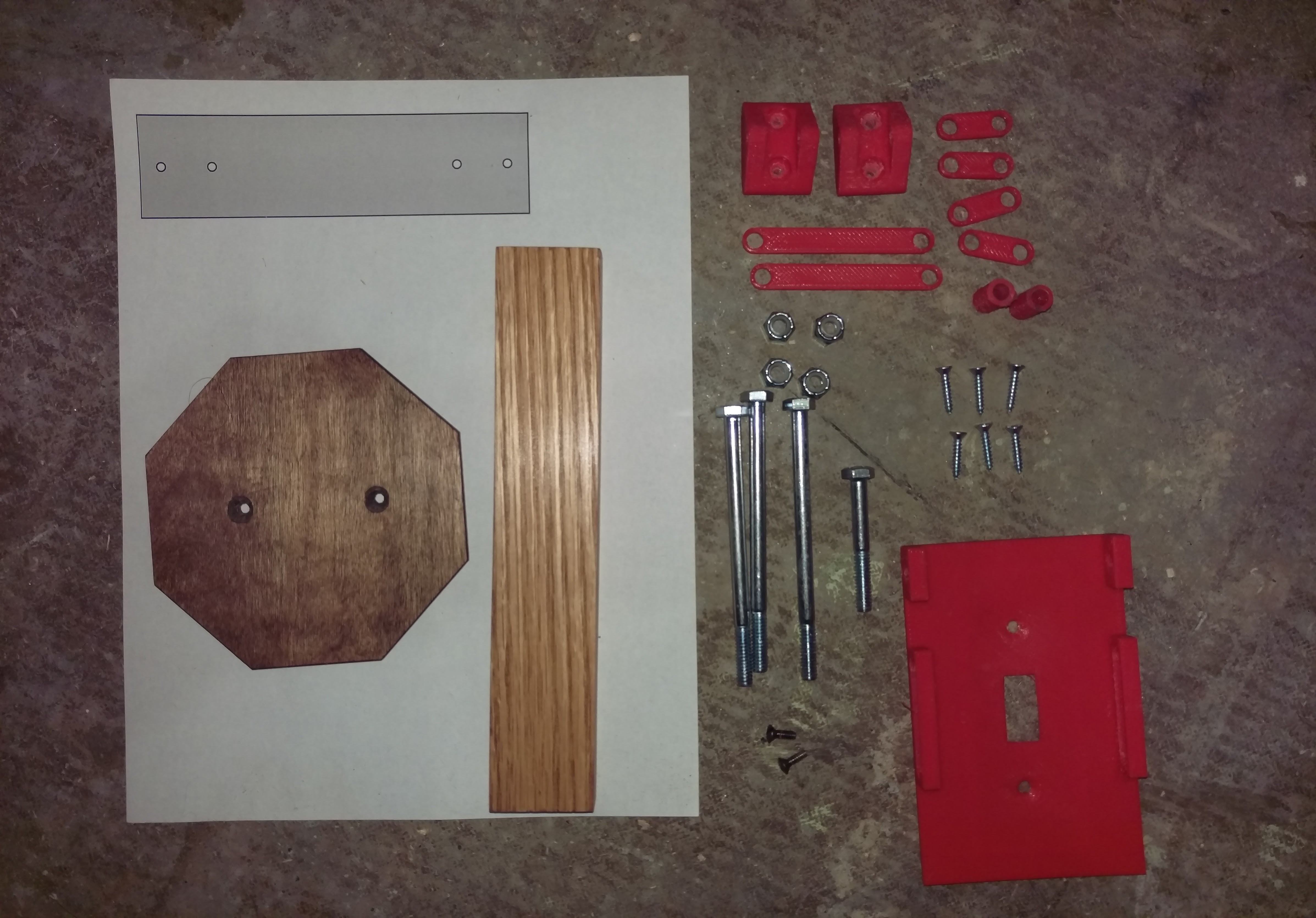
- Requires:
- ¼ - 20 x 4" Bolts (3)
- ¼ - 20 x 2" Bolts (1)
- ¼ - 20 Nylon Lock Insert Nuts (4)
- #6 x ¾" Screws (6)
- #6 - 32 x ½" Pan Head Machine Screws (2)
- Light Switch [110v/220v] (1)
The lever is made of ¾" stock measuring 1 ½" x 8". The stop sign paddle measures 4 ½" across and uses #6 screws to hold everything in place. The stop sign paddle is made o f .2" birch plywood. Holes in stop sign birch were countersunk with a ⅜ bit. You can also print the lever with the paddle using the provided STL.
- STL Files:
- Switch Plate x1
- Hinge Bracket x2
- Short Linkage x4
- Long Linkage x2
- Spacer x2
- Lever/Paddle x1
Preparing the Lever
Skip this section if you are printing the lever!
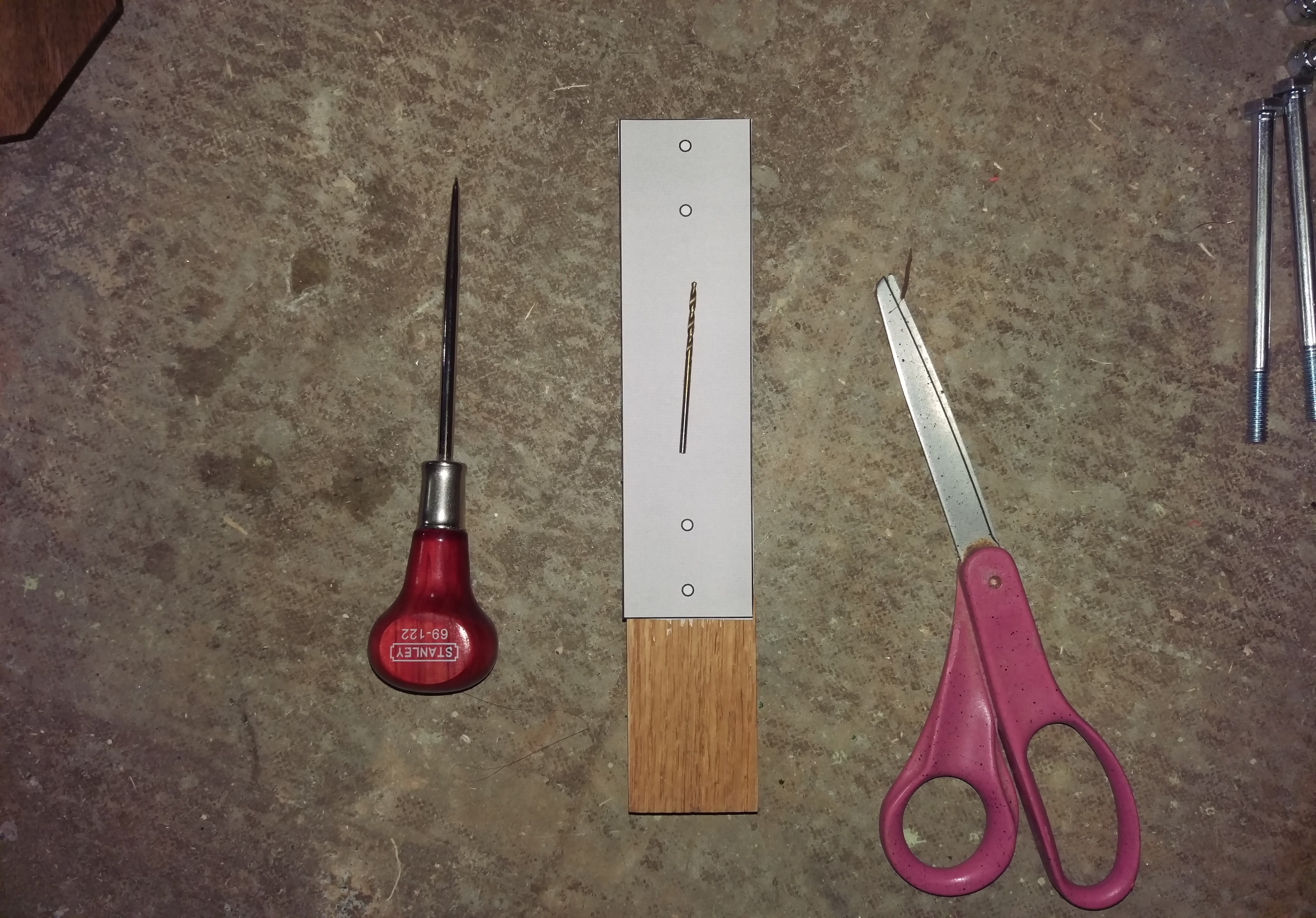
Using a scratch awl, a 3⁄32 HSS drill bit, scissors and some tape, mark out the holes using the Drill Guide. Drill the hole approximately halfway through the lever.
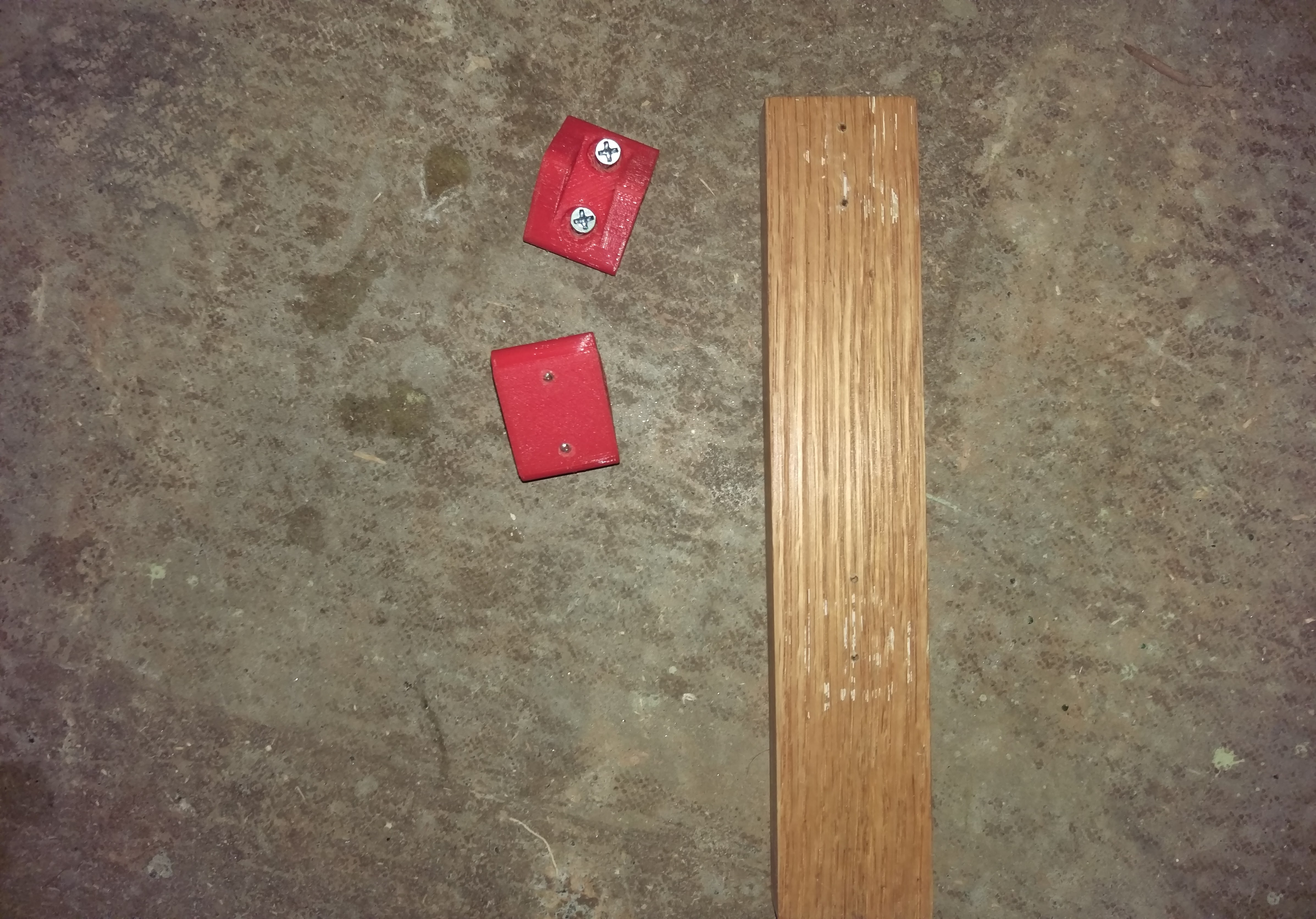
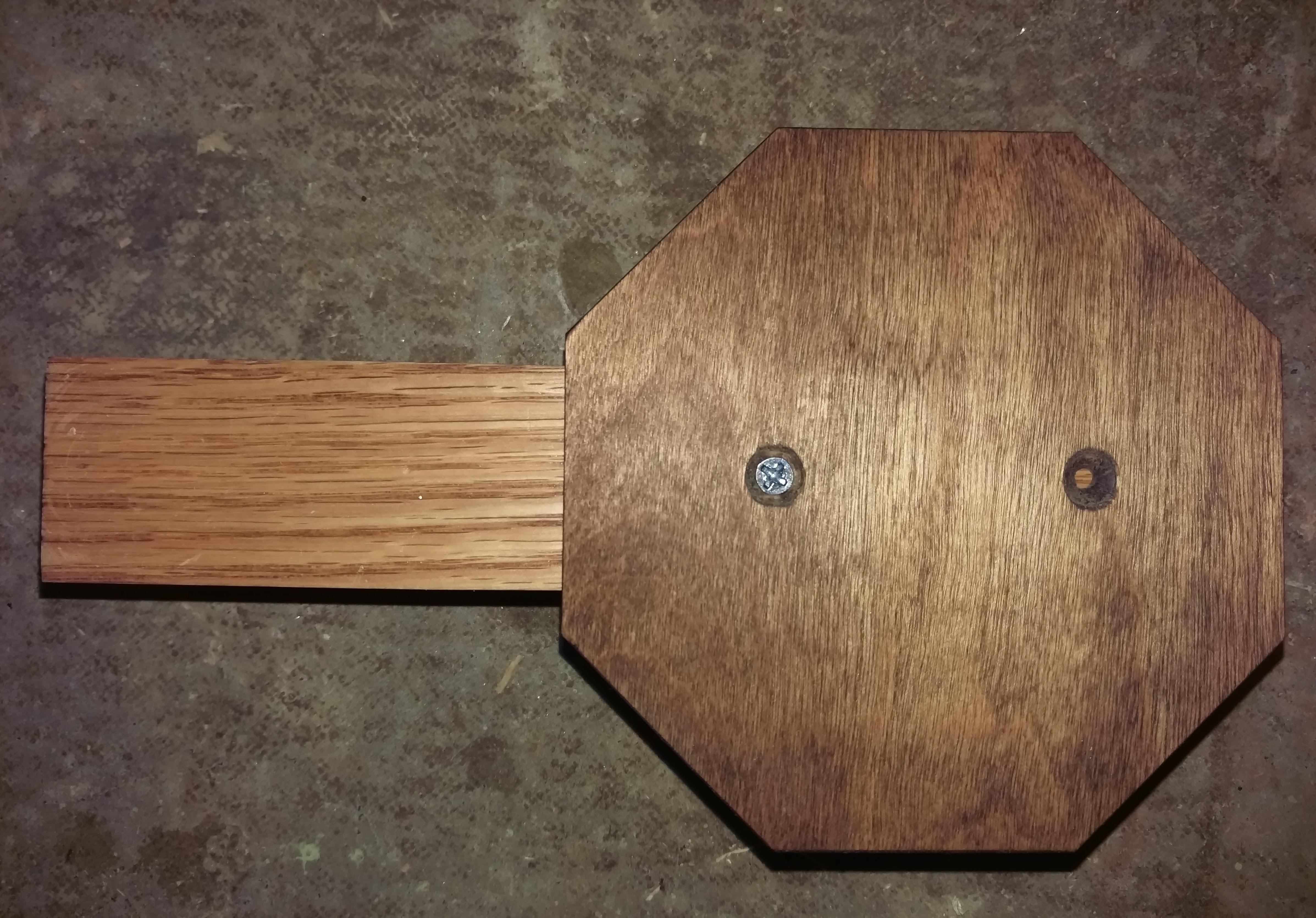
Pre-drill the holes in the rear of the lever and start the #6 screws in the Hinge Bracket pieces. Line up the screws with the holes.
Drive the #6 screws in by hand until there is no gap between the hinge and the wood lever.
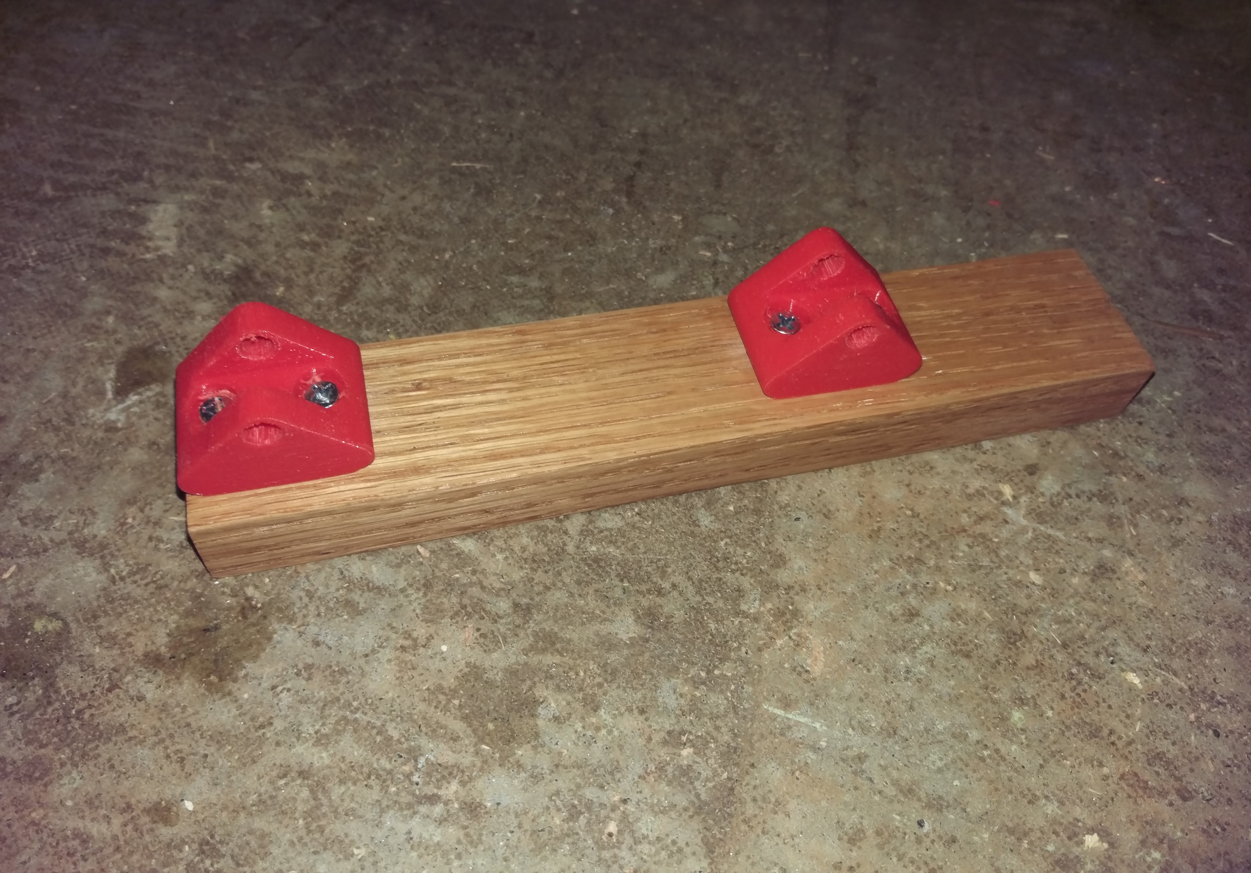
Turn the lever over. Line up the Stop Sign birch piece with the lever. Mark one hole with the scratch awl and pre-drill again using the 3⁄32 HSS drill bit.
Hand-tighten the first #6 screw just enough to keep the Stop Sign in place, but able to be adjusted square to the lever.
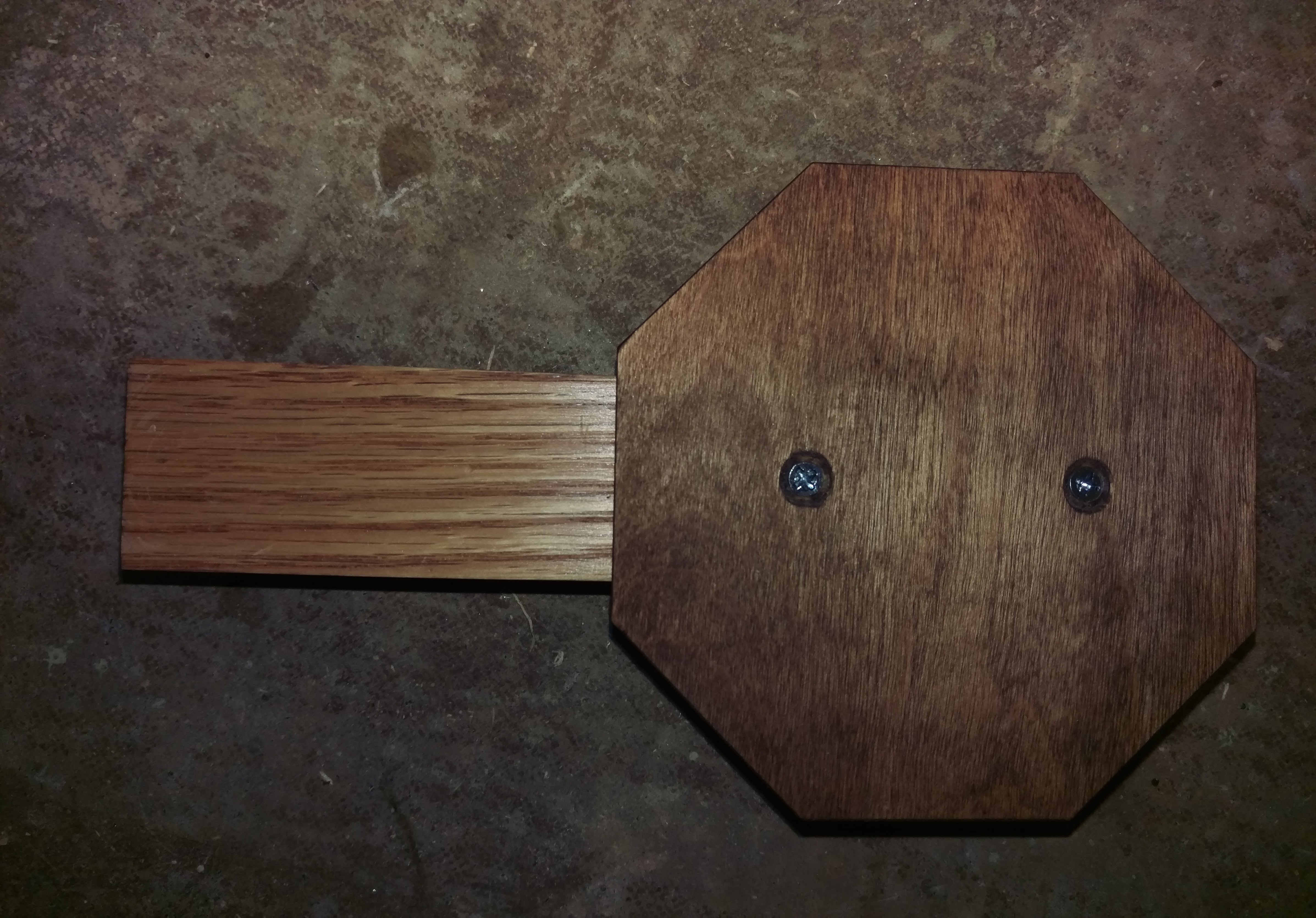
Repeat the same process for the next hole with the Stop Sign in place. Pre-drill, then hand-tighten both #6 screws into place. The "paddle" is now complete!
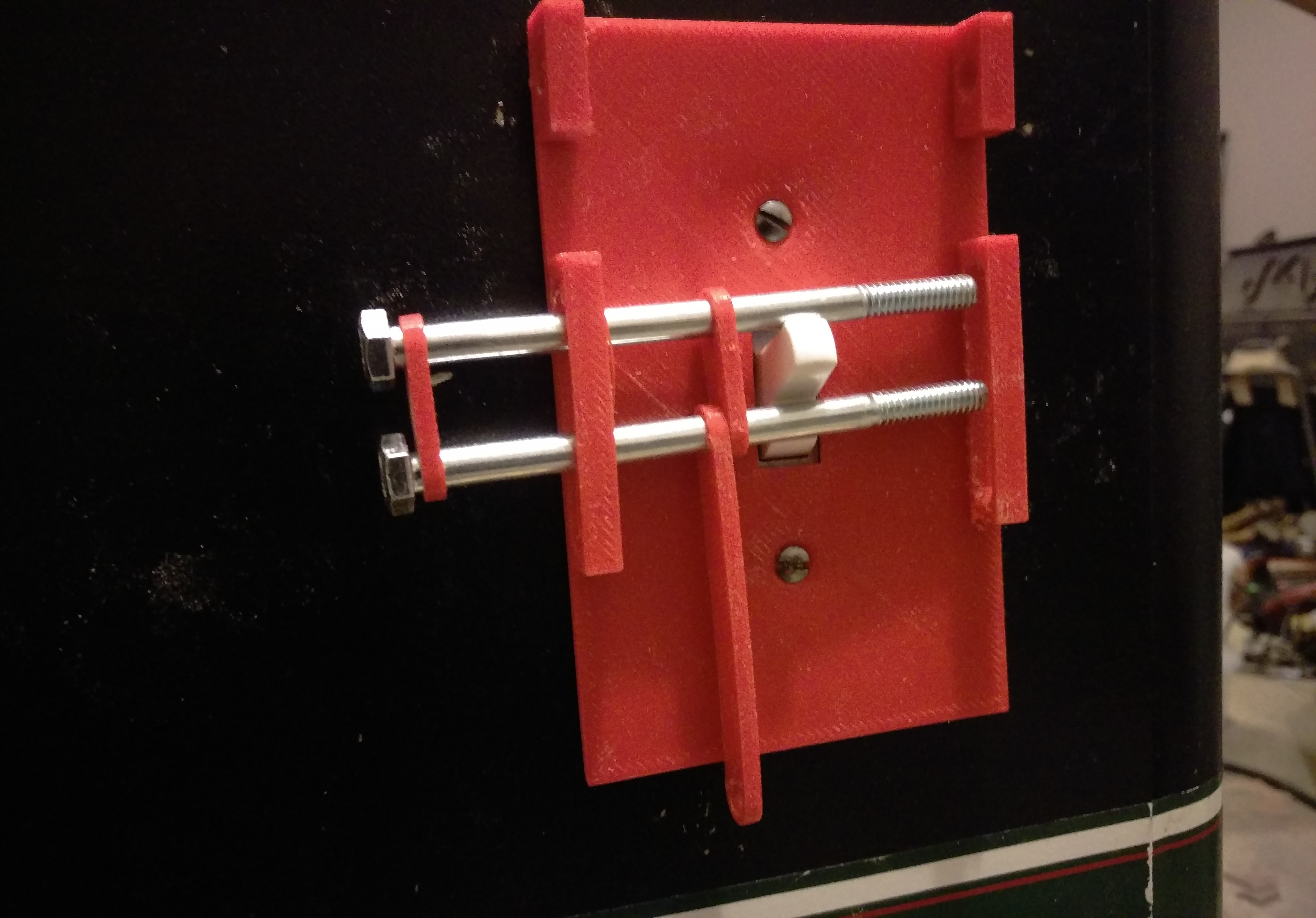
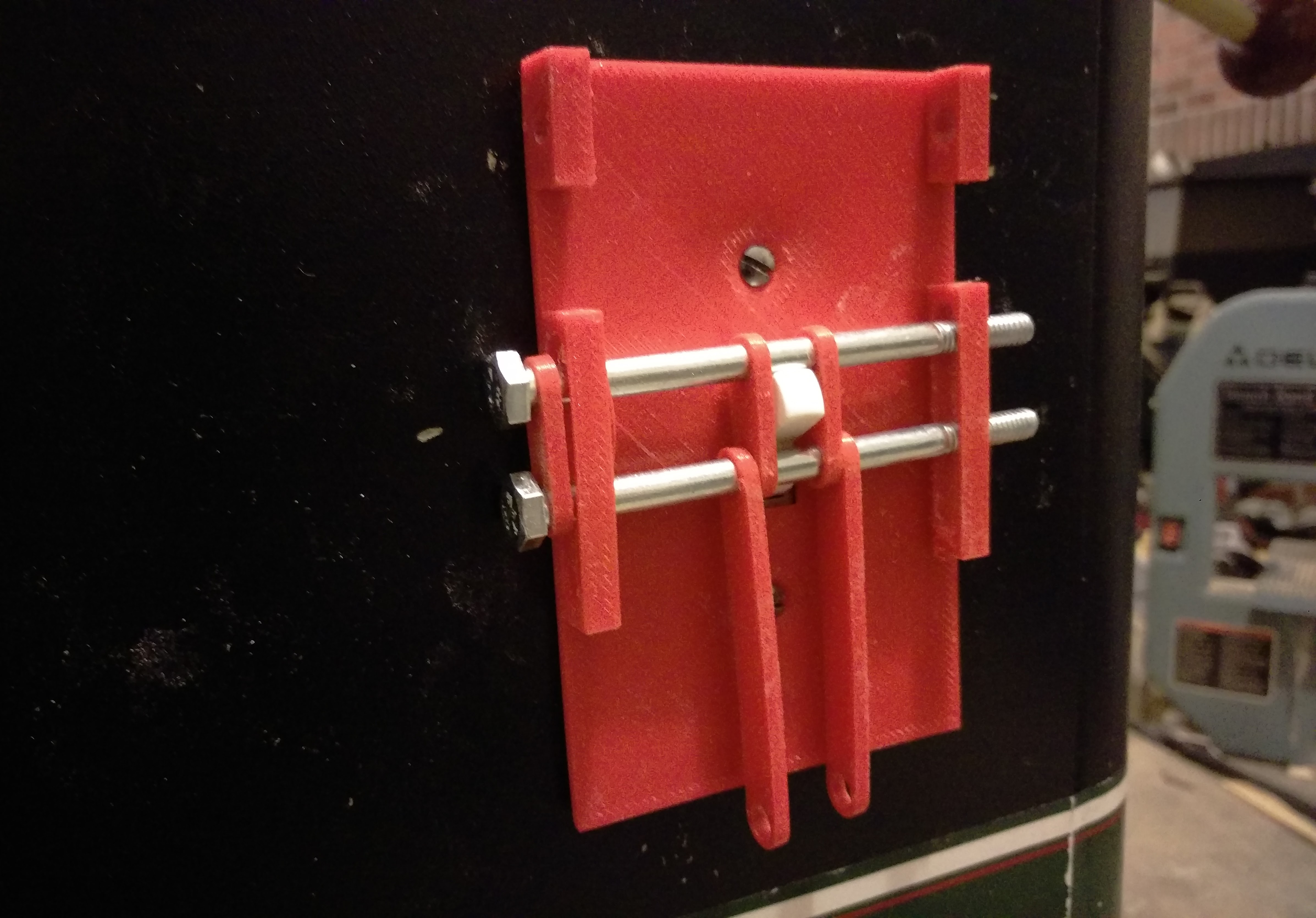
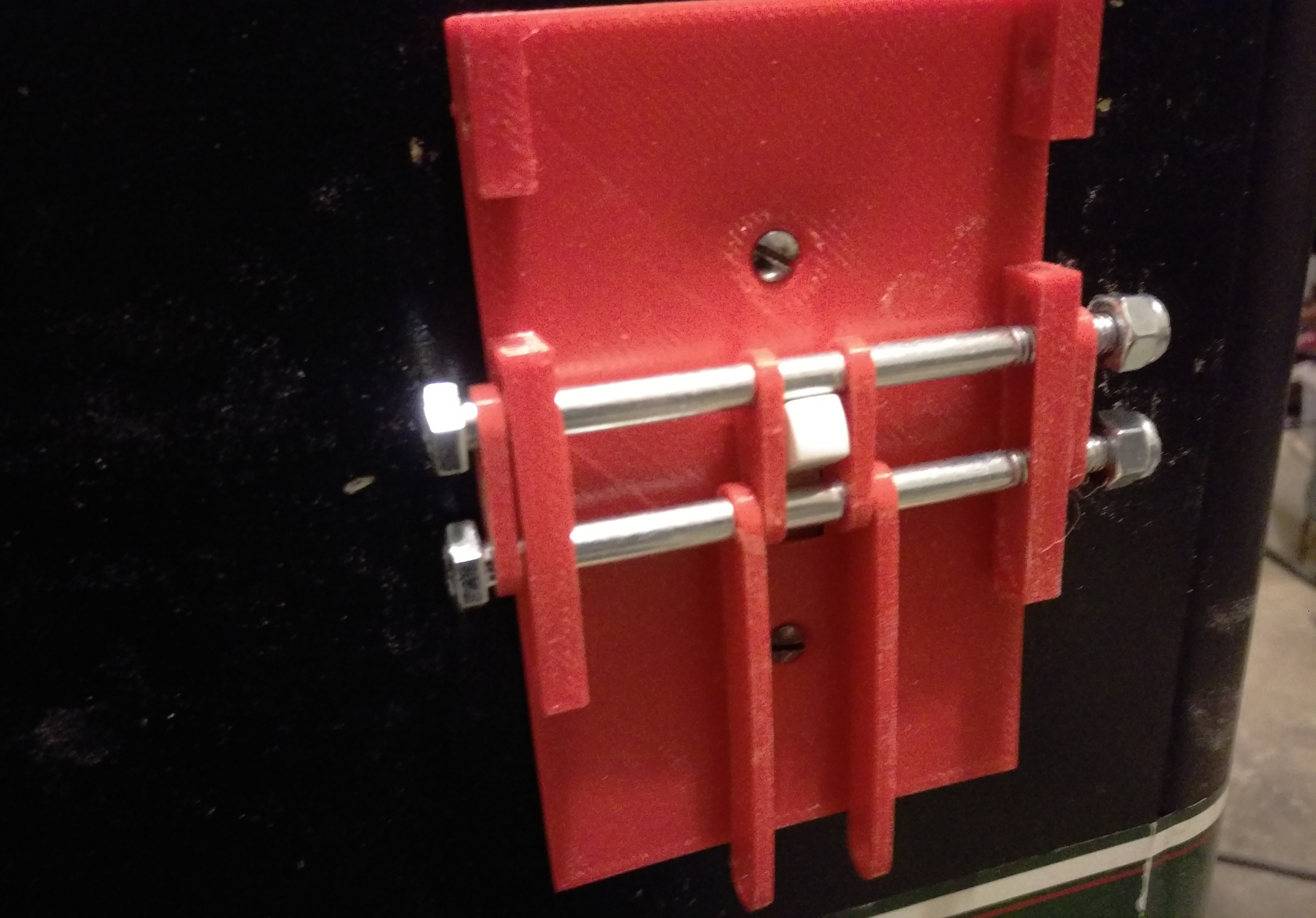
The Switch Plate
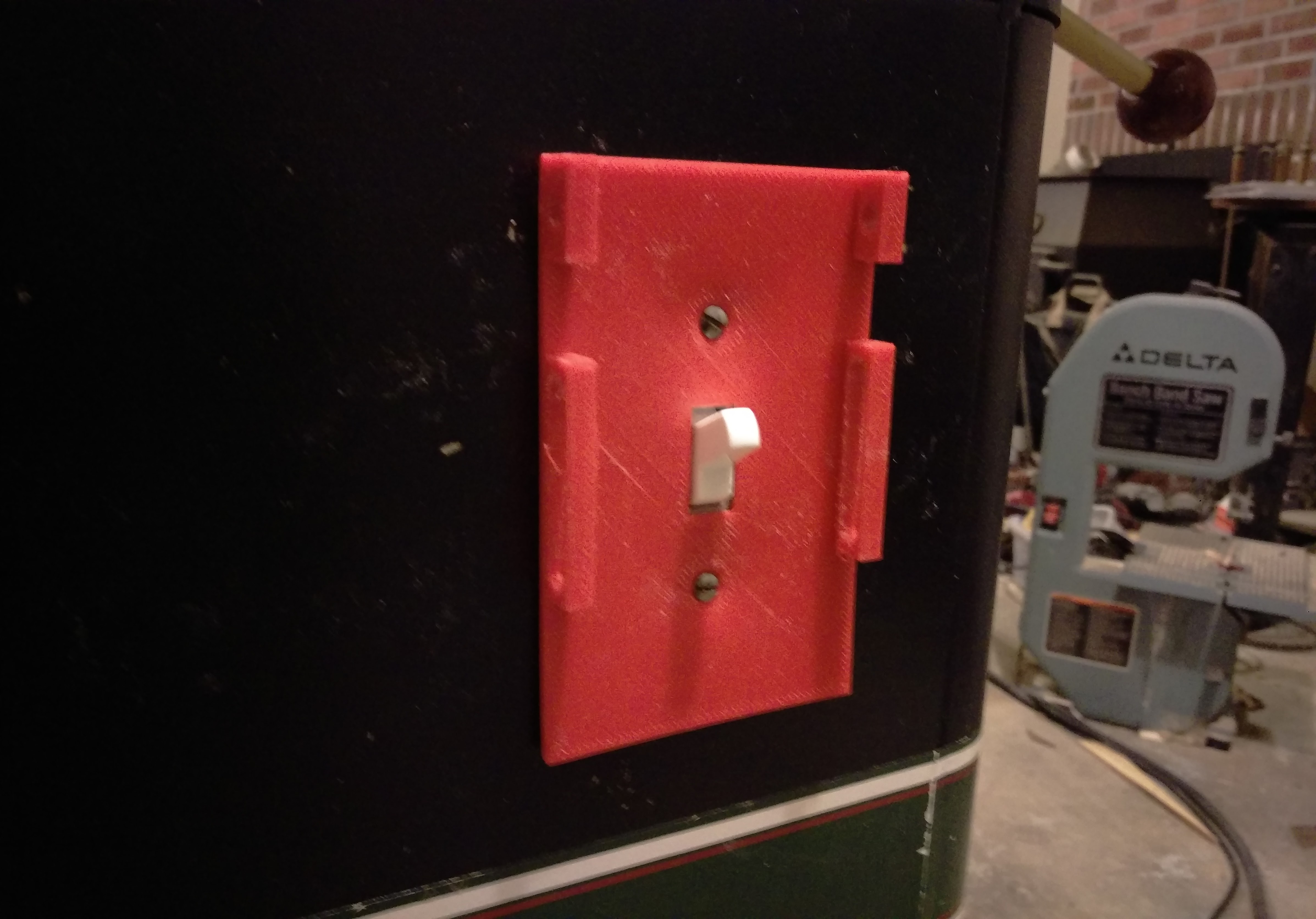
Place the Switch Plate over the light switch using the #6 - 32 x ½" Pan Head Machine Screws. Remember to install your light switch upside down before placing the Switch Plate on the light switch.
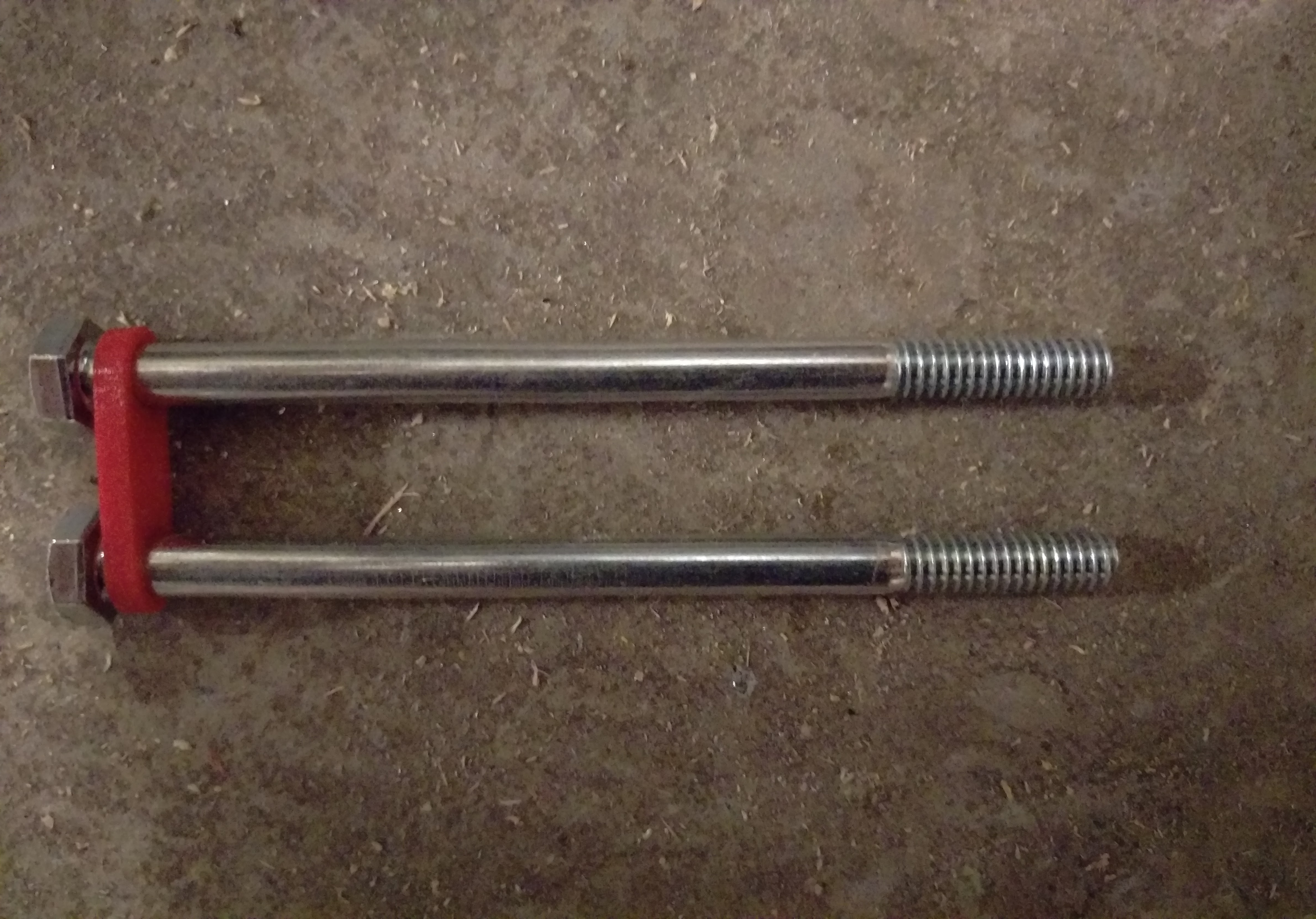
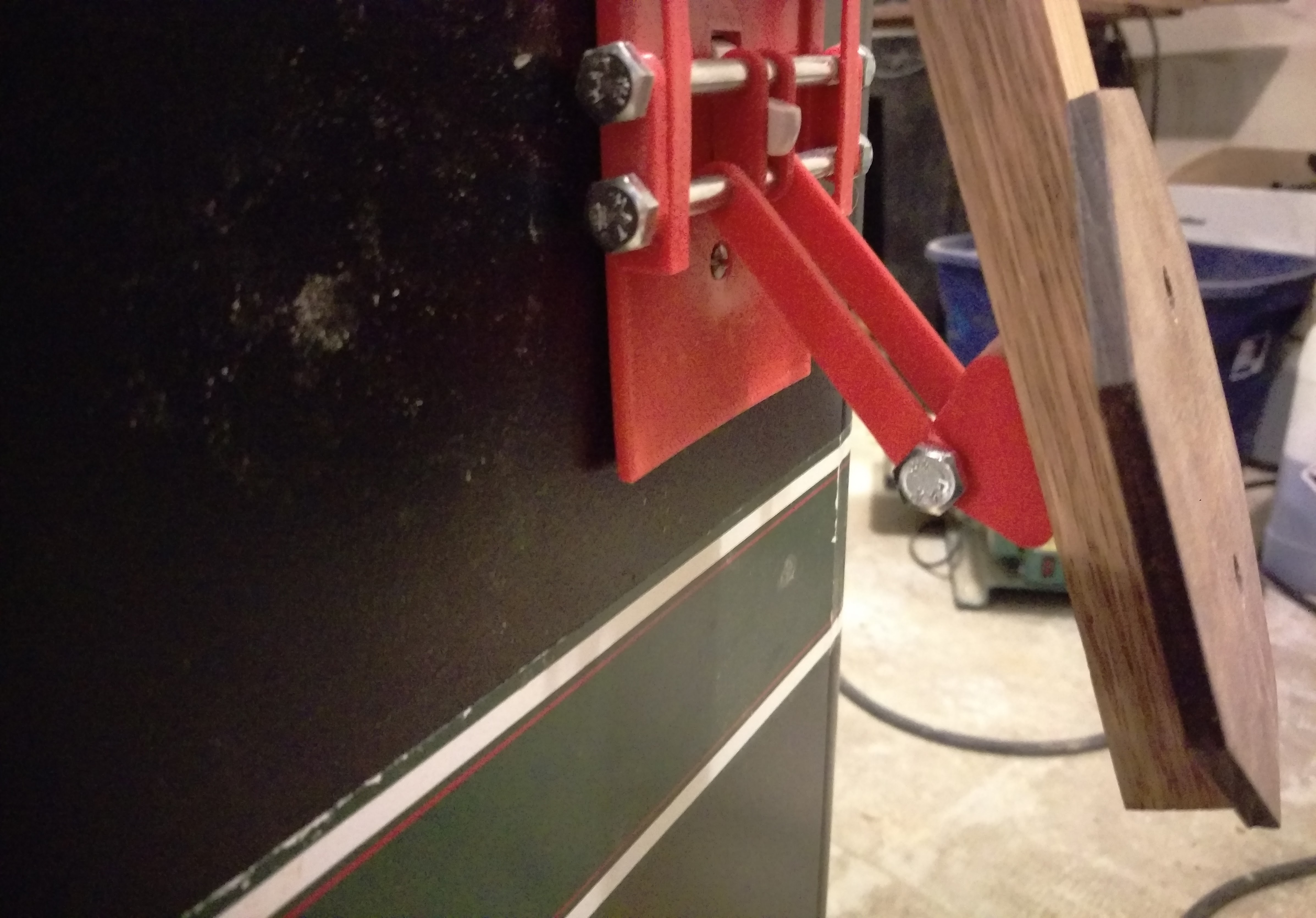
Slide one of the Short Linkages over two of the ¼ - 20 x 4" Bolts. Make sure the linkage is pressed against the head of the two bolts.
Place the two bolts through the wider slot in the Switch Plate. While inserting, place a Long Linkage on the lower bolt and then a Short Linkage on both bolts.
Continue to feed the bolts past the switch itself. Add another Short Linkage and a Long Linkage to the lower bolt. The linkages should be mirrored around the light switch.
Finish guiding the bolts through the opposite slot in the Switch Plate. Slide the last Short Linkage over the two bolts and cap with ¼ - 20 Nylon Lock Insert Nuts.
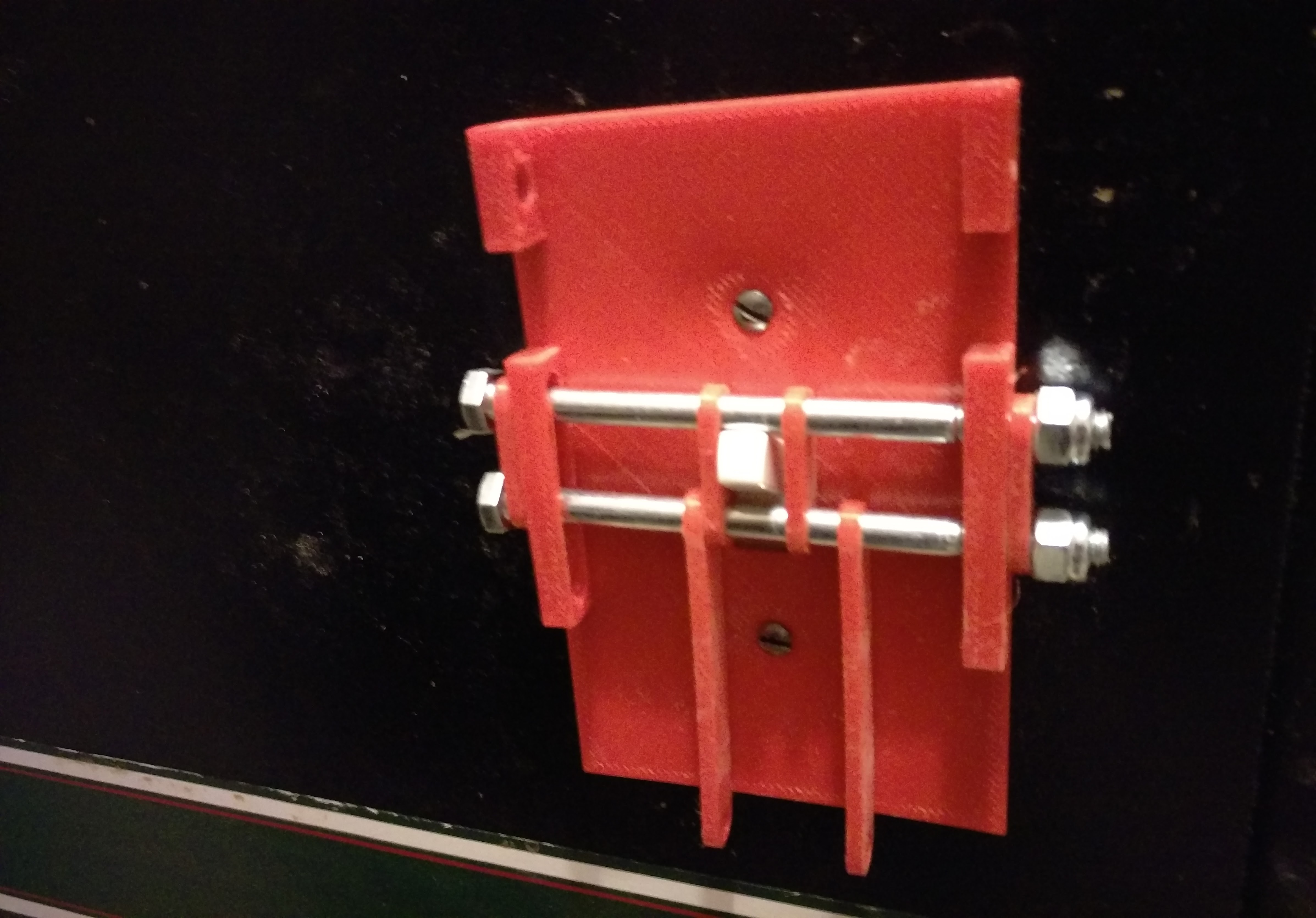
Using a socket wrench, tighten the lock nuts onto the bolts. Do not over-tighten these nuts. Allow for the two bolts to slide up and down in the slots, but make sure they do not wiggle from side to side.
Connecting the Lever to the Plate
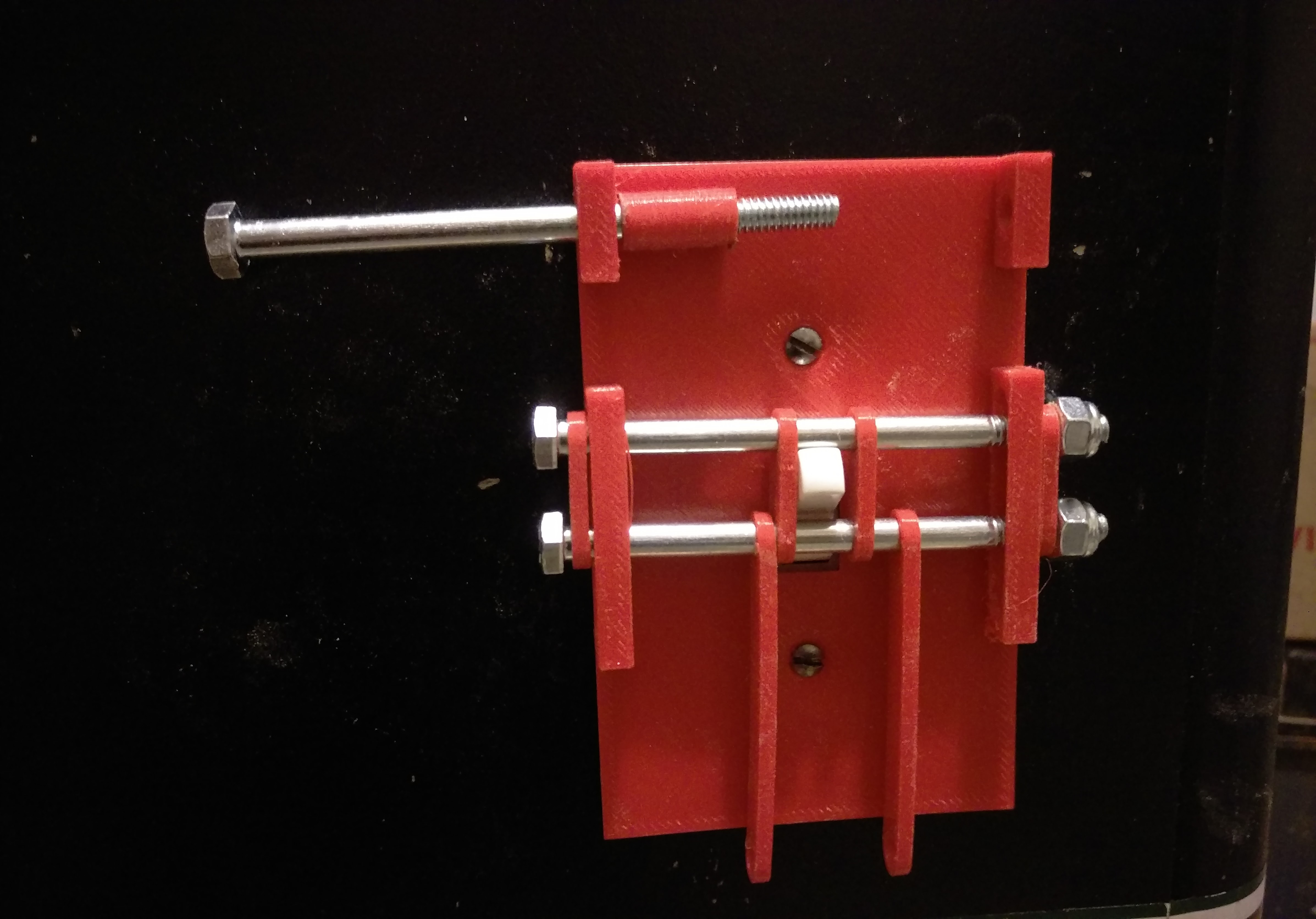
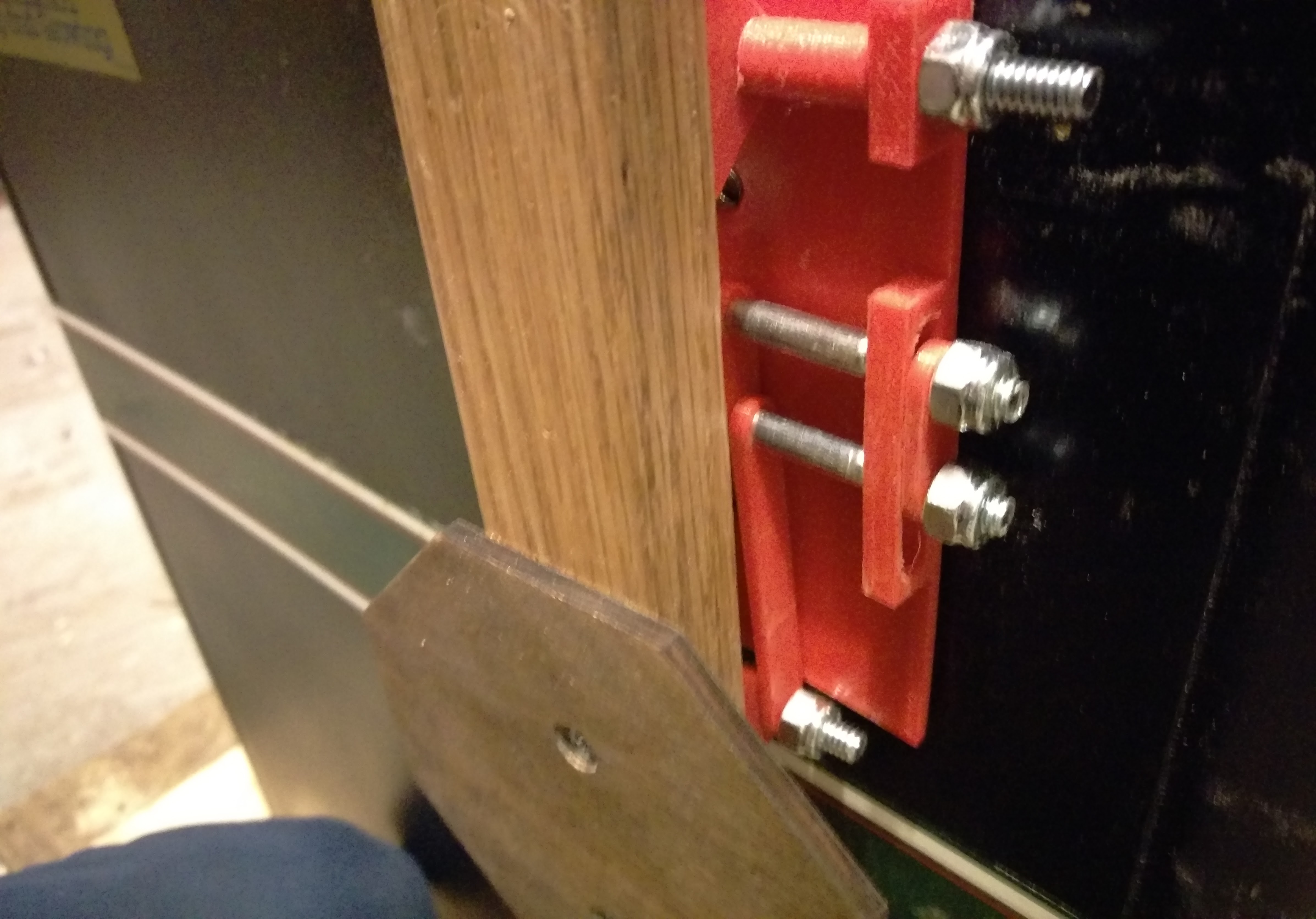
Utilizing the last ¼ - 20 x 4" Bolt, place it through the top hole in the Switch Plate, followed by a Spacer.
Slide the lever onto the bolt next through the Hinge Bracket on top of the lever. Follow this by another spacer, then through the opposite hole in the top of the Switch Plate.
Using a socket wrench, tighten the ¼ - 20 Lock Nut onto the bolt. Do not over-tighten this nut. Allow for the lever to swing up and down, but make sure it does not wiggle from side to side.
Making sure your machine is unplugged! Using the ¼ - 20 x 2" Bolt, slide it through the bottom hole in the Long Linkage. Continue to feed the bolt through the bottom Hinge Bracket on the lever. Lastly feed it through the other hole on the opposite Long Linkage.
Using a socket wrench, tighten the ¼ - 20 Lock Nut onto the last bolt. Do not over-tighten this nut. Allow for the lever to swing up and down, but make sure it does not wiggle from side to side.
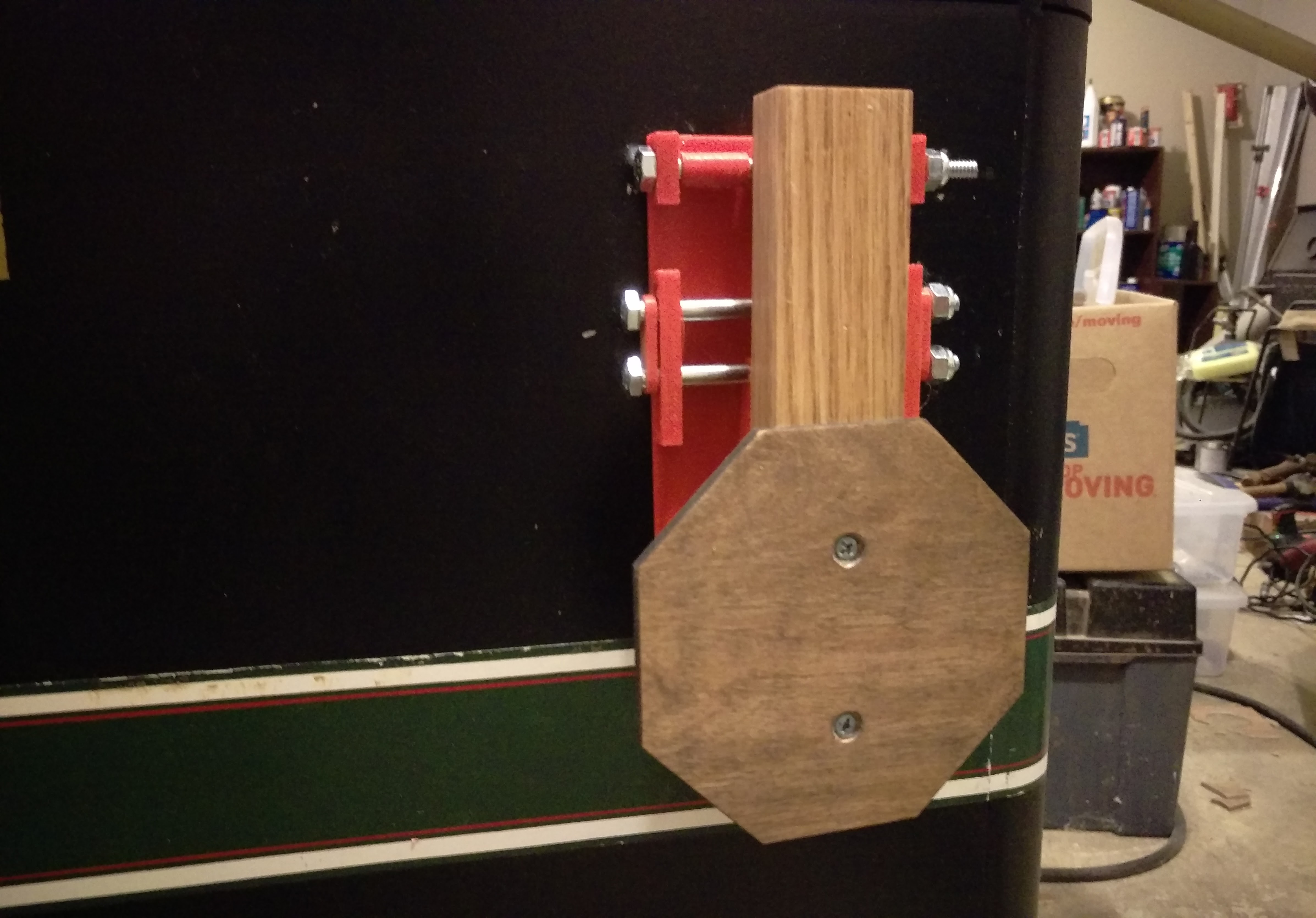
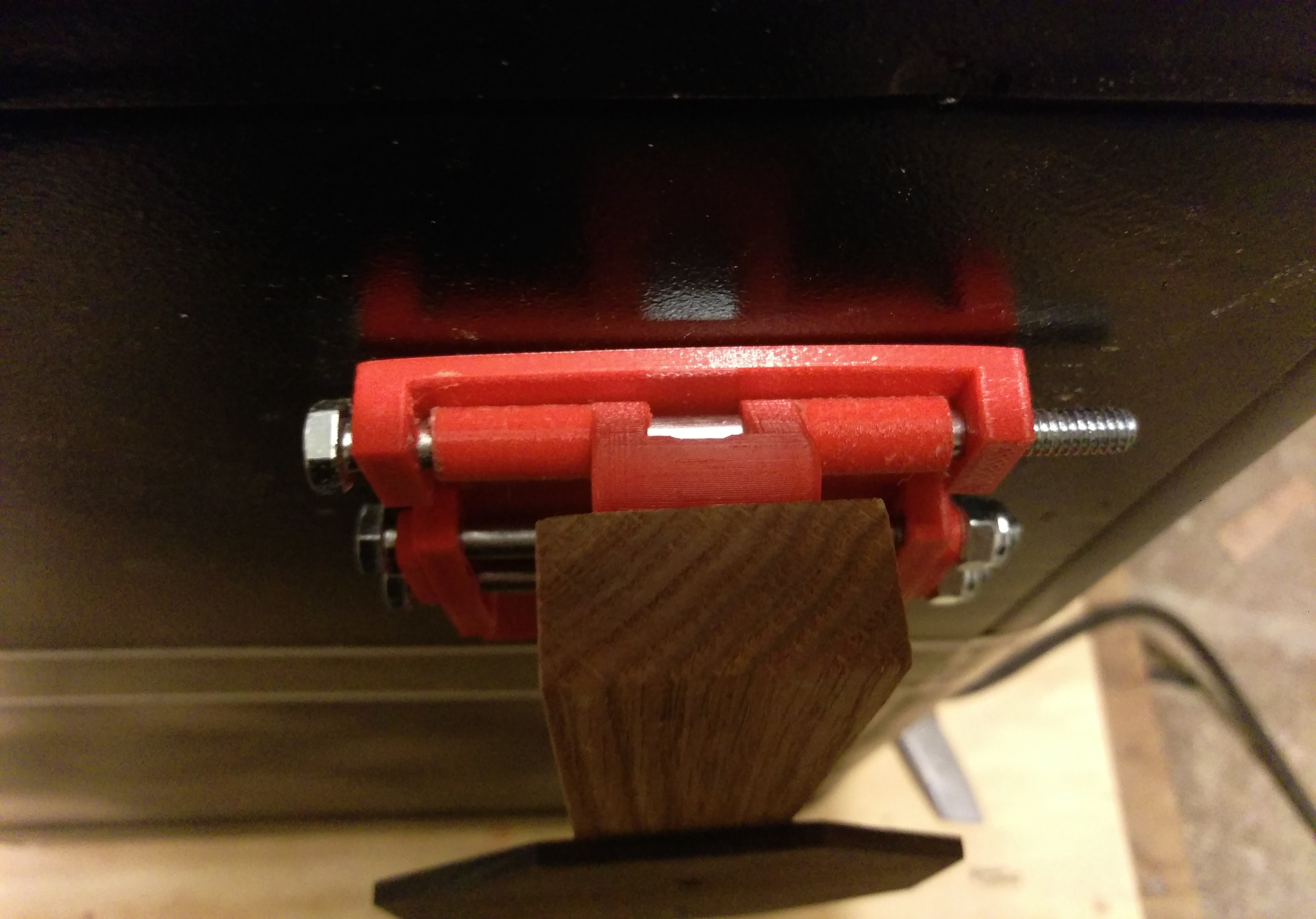
Your final paddle switch in the "off" position!
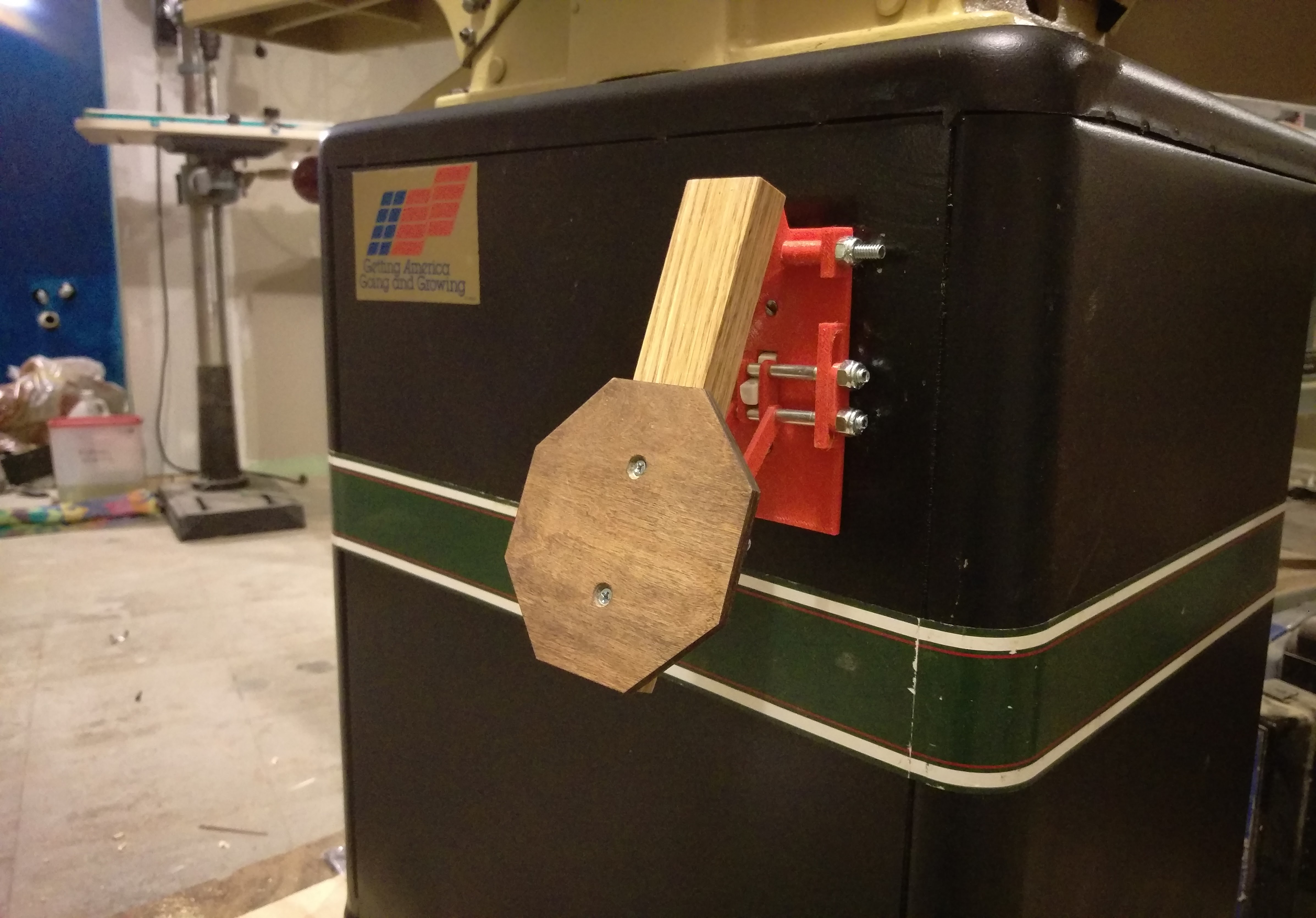
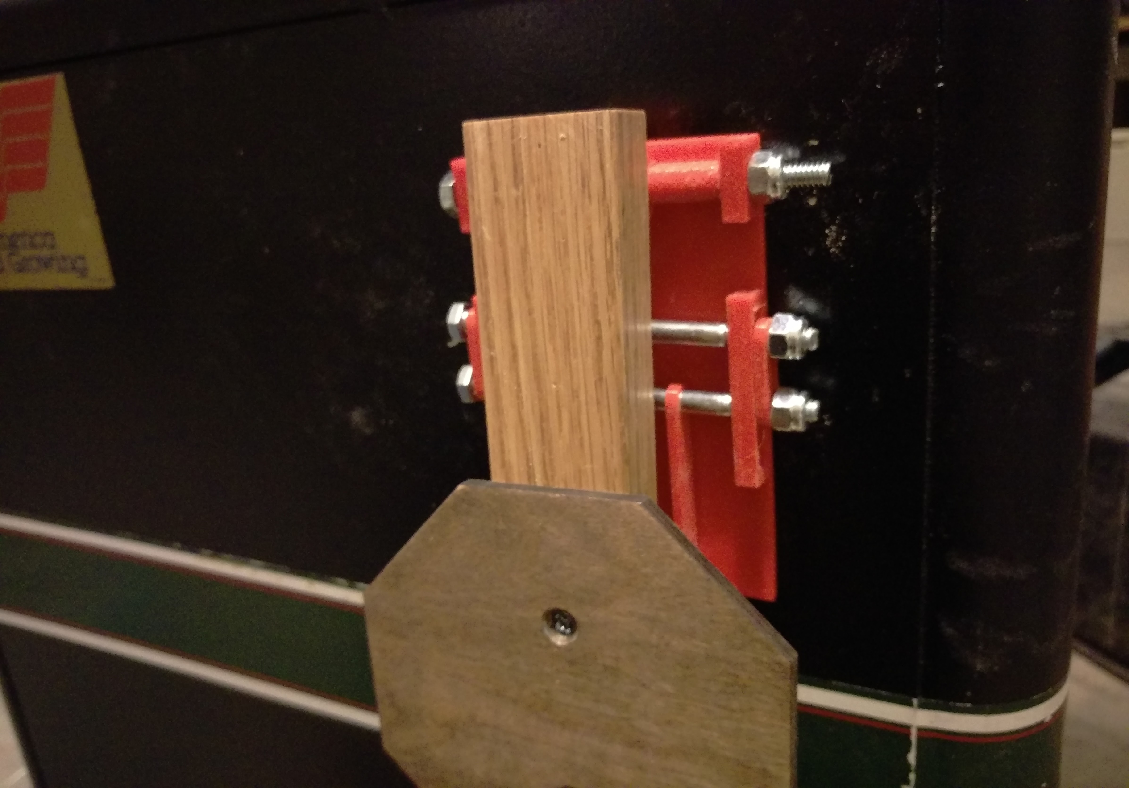
This is the completed Paddle Switch in the "on" position.
Connect
Designs by Eric Bredder. 2017. Site designed from Skeleton. Icons by FontAwesome.